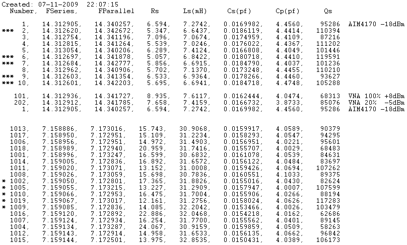


You measure this (along with the series resonant frequency) with a Pi network the legs of which are resistors. So, in a 5 crystal ladder you should have 3 groups (1 for the centre +2x2 for the other 4 places).Īs you can not practically have crystals matched to the same Hz, there is a try and error job to find the best permutation (which crystal to what position).ģ) More important to 2) is to select crystals that have low series impedance at resonance. The trouble with this is that the position of each crystal in the ladder is important. If you are patient enough, try adjustable trimmers in parallel with fixed capacitors.Ģ) Matching all the crystals as per their resonance frequency is a good thing, but with crystals up to 200-300 Hz apart you can have a better shape with not significant increase in passband ripple. In the quest for a better 6:6O* db shape factor these things I remember:ġ) The shunt capacitors better have an increasing value from the ends to the center of symmetry.


They are 3dr overtone, hence their fundamental freq is a bit higher than 9 MHz. Prior to this the "lattice" topology (half or full) was mainstream for diy receiver builders. It was the time the "ladder" network started appearing in radio magazines. Next job is to measure some parameters of the crystals and then use Dishal to give me better cap values and to built it again, to see if I can make it better with much less ripple and with more theoretical shapes.ĭid what you are doing during the early 70s. This was graphed prior to terminating the filter with 1K impedance, so it might be a bit wrong town, its something i will have to redo. Using the lowest output setting on my signal generator, a series of measurements were made, converting the amplitude millivolts to Db and each filter was plotted and graphed in a spread sheet.ġoopf cap version, data below -45db is not all that accurate as my scope was picking up general rf noise to the tune of 10mv, filter is about about 900hz wide. Went with the super ugly design method on a scrap of board thats been used far to many times for other experiments. I made 2 identical filters, one with the 100pf caps and another with 50pf caps. So time to start playing with crystal IF filters.Įverything starts with a schematic, no i did not design the filter using software, nor did i measure the emotional parameters of the xtals to match them up, just went hit and miss to see what happens. After having lots of success with DC receivers, i guess the next logical step is to move to a superhet design.


 0 kommentar(er)
